

Complete instructions on how to make an automatic indexing system for a model railroad turntable.
The system shown below allows indexing up to 12 tracks.
For information about the motor control system, go here. bbbbbb
For information about a drive mechanism, It ignores the drive mechanism go here. Turntable Drive Mechanism.
System Overview
IR Sensor emitters are mounted in holes around the turntable pit. For this system there are a total of 12 positions.

The emitters are located on center line of tracks.
A receiver is located on the center line of the turntable, one on each end.
The heights of emitters and receivers are equal. Each should be hooded with shrink tube.
A rotary switch chooses which emitter is active.
The turntable motor runs until a receiver is triggered by the active emitter. The motor control circuit is described here. MMMMM
The only critical thing is the LED sensors location under the bridge, they must be identical in location, within 1/64″ or better for the bridge position to be accurate on both ends.
Tracks can be tweaked to set perfect alignment.
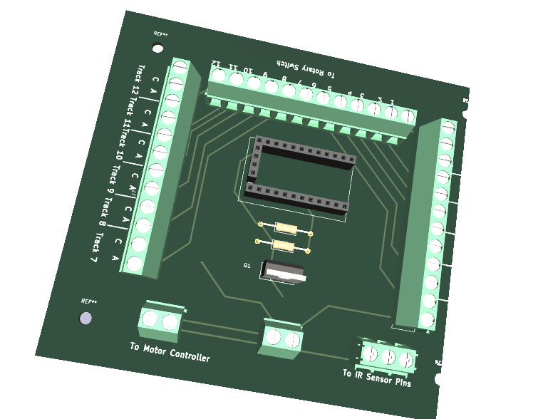
Circuit Board
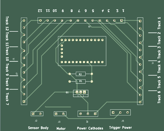
Elements
Circuit Board
Resistor 270 Ohm 1
Resistor 10k 1
Arduino mini pro 1
IRF540N Mosfet 1
2 pin screw terminal 20
3 pin screw terminal 2
12 point rotary switch 1
Pin header 1
DuPont pin socket 1
IR Emitters 12
IR Receivers 2
You can get what you need and that includes the code and an instruction guide, in one place . Click here.
Wiring
All connections between parts are made via traces on the circuit board. All that you have to do is follow the assembly process below.
Assembly
The circuit board shows exactly where the elements are placed on the board,
So it is a simple matter of inserting the parts, soldering them in place with a fine point soldering tip on which there is a minuscule drop of solder and finally trimming off any protruding wires or pins to a comfortable length.
The screw terminals come as 2 pin units. They are designed to be joined by using the slots on each side. So, for example to make a 4 pin screw terminal, join two two pin terminals.
The Arduino mini pro is fully programmed.
Installation.
Your indexing circuit will send a signal to the motor controller that tells it whether the motor should run or stop.
The receivers are connected to the wires at the top of the drive mechanism drive rod.
The anodes of the emitters are connected to the rotary switch.
The cathodes of the emitters are connected to the IR Sensor
Operation
This storm is controlled by a manual switch. The connections are labeled SW1 and SW2 . To control it via another micro controller just connect the trigger from that controller to SW1 . That switch is usually located on a control panel which is likely to be some distance from the circuit board.
Attach the speaker to S+ and S-. The + and – match those on the speaker. Speakers have an upper limit of 3 watts.
If you wish more volume, add a 5v amplifier. How to do that is here.
TX and RX are connections for a Bluetooth module. By using such a module you can play sound on a Bluetooth speaker that you place at a removed location. How to do that is here.
Connect to a 5 volt power supply via the labeled terminals.
Feedback
Please let us know if this page has been helpful And if you have questions or suggestions, use this spam free system.