

How To Make An Inexpensive DC Model Train Power Pack
What’s In This Page
 This page is a step by step DIY guide for making power pack for DC model trains. It can be made as either a single or dual cab unit. A video demonstration of it operating is included.
In addition to complete instructions in this web page, you can download this complete instruction guide so that you can 1) conveniently work off line and 2} keep it in your library so you always have it immediately available. To download it free, click here.
Overview
The controller allows you to control speed and direction. LEDs show the chosen direction.
The motor controller used is able to be used with an input voltage of 30 volts. But since most model trains operate at 12 volts, we shall concentrate on 12volts.
 Also, we will focus on making a single cab power pack. We will also show you a single operator dual cab model that you can make by simply duplicating a single cab in a larger box. For two cab two operator control, use two singe cab controllers.
If you are interested in 2 cab operation, here is how to wire your layout. Click here.
How It Works
Before you jump off on a project, you want to see it work. This video shows you just that. Click Here.
Materials Needed To Make A Power Pack
This shows the basic parts that you need. A motor controller, reversing switch, speed controller and power connectors.
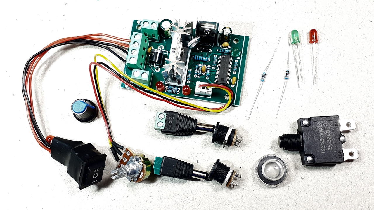 A motor controller that has connected to it a switch for reversing motor direction and a potentiometer that is used to control motor speed,
2 5mm LEDs. One red and one green.
2 1k resistors that allow the LEDS to operate to 12 volts. LEDs will light depending on direction and the brightness will vary with speed.
A 3 amp circuit beaker.
2 male barrel jacks
2 female barrel jack plugs.
Shrink tube – red and black
Power Supply – You should use a a fixed voltage power supply that takes house current and converts it to a fixed DC voltage. This fixed voltage that you need varies from gauge to gauge. G-Scale trains typically run with up to 24 volts, HO-Scale is up to 16 volts when the engine is heavily loaded but normally 12 volts is sufficient. N-Scale needs 10 or 12 volts.
On our shelf layout we use 12 v DC supplied by a 2 amp wallwart.
You can use anything from a converted computer power supply, a laptop computer supply to a wallwart. These can supply 3 and more amps, more than enough for a good sized layout.
For floor operations, a wallwart is a convenient choice.
Wire – Any flexible wire capable of carrying 2 to 3 amps. Current rating depends on the size of your layout and power requirements of your locomotives.
Collecting The Parts
All parts are readily available on line. I will note that shipping costs and expended time can add up when you buy individual pieces.
As an alternative, you can get the parts in a time and work saving discounted package at PolandsBest. Click here to check the details.
Our Goal
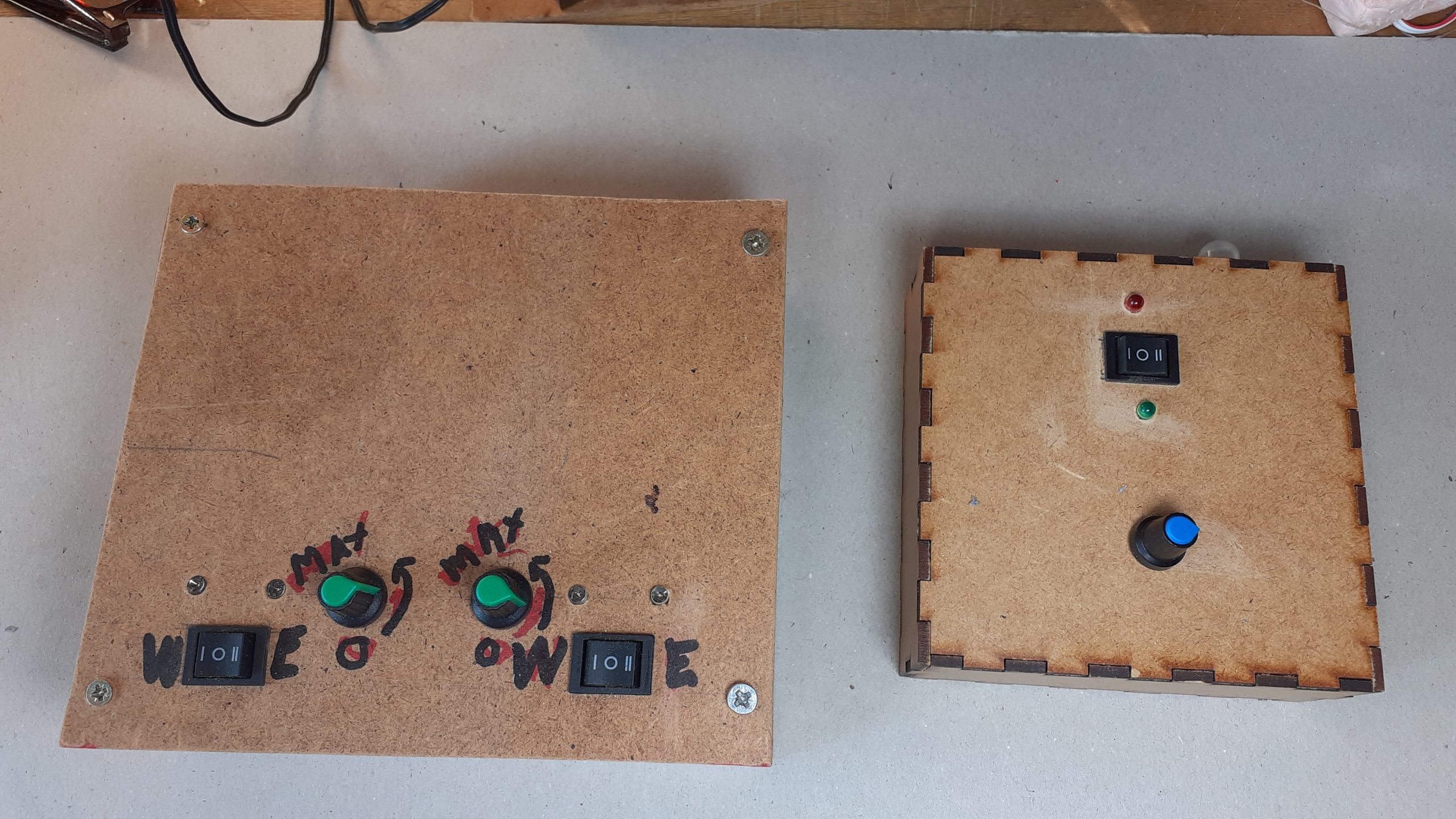
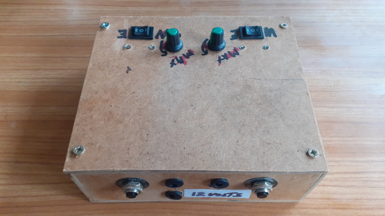
Shown is a single cab controller.
The motor controller and circuit breaker are in a laser cut box. That box is a optional choice with the kit. Alternatively, you can either make your own box or use a commercial container.
The LEDs are on either side of the direction switch.
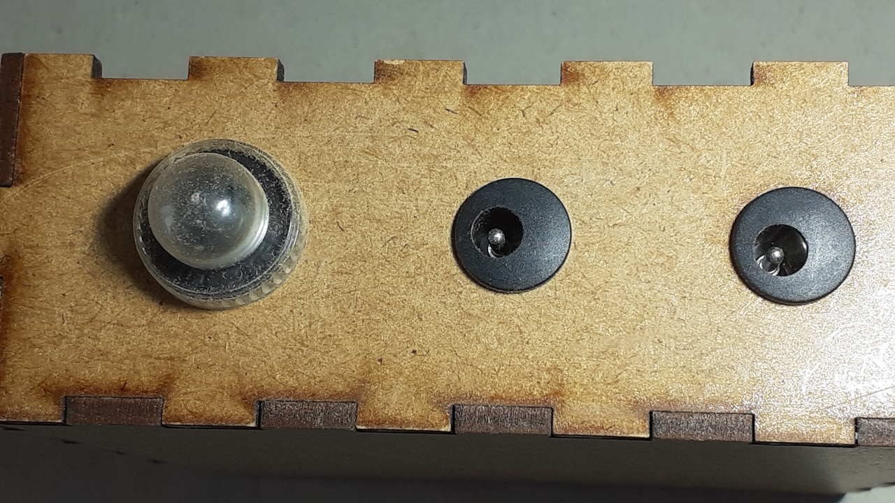
The female barrel jack receptacles and the circuit breaker reset button are on the side of the box.
The speed controlling potentiometer is placed for convenient operation.
Wiring The External Connections
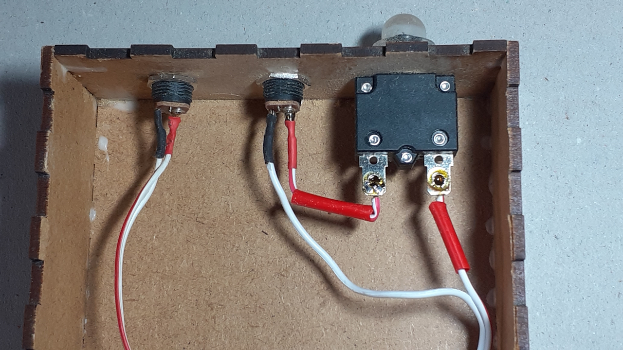 The first step is to set up the external connections.
Note the the circuit breaker must be oriented so that the tab that is labeled “load” connects to the female barrel jack,
 Side View
Add Resistors To LEDs
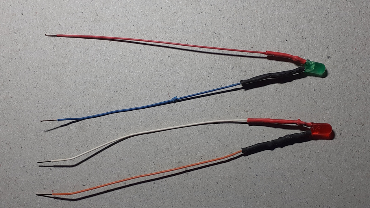 Add wires to LEDs. Include a resistor on one leg. Add the red and black shrink tube on the appropriate leg.
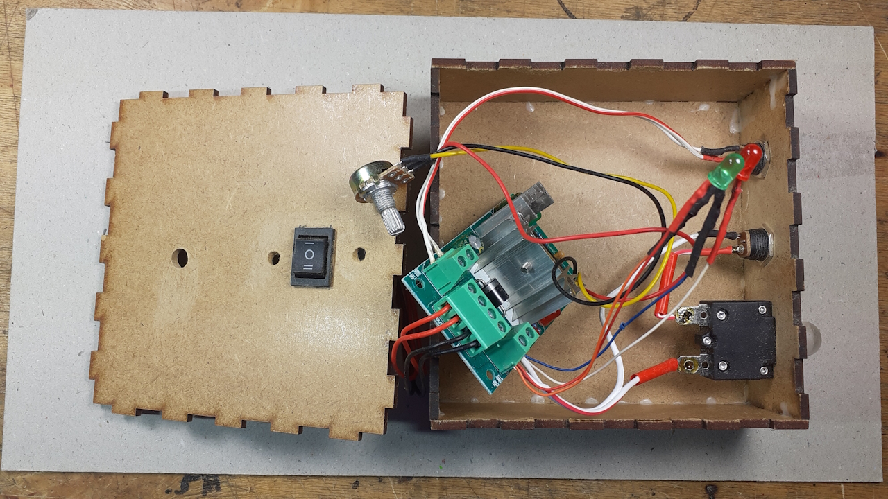
Final Wiring
The image show the wiring. A detailed explanation follows.
 The power supply is connected to the terminals labeled + _.
Connect the circuit breaker tab that is labeled “load” to the output female barrel jack. Connect the other side of the circuit breaker to M1.
Connect the other side of the output female barrel jack to M2.
Don’t worry about polarity. It will change with direction switch position.
Connect the anode of one LED and the cathode of the other to M1. Do the same for the other on M2.
Adding The Cover
 Insert the potentiometer control pin through a hole in the top. Do the same with the LEDs and switch.
The switch has two red and two black leads. Connect the two red to out. Connect the black to black.
Close the top.
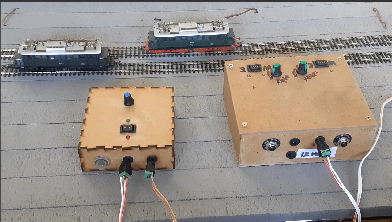
The Power Pack
This is a single cab unit.
If you want to have two operators, build two.
Once again, here is how to wire for two cab operation. Click here.
Single Operator Two Cab
 There are two ways to approach two cab operations. One operator can control both cabs or there can be two operators with each controlling a single cab.
This shows a single operator setup.
 The external connections are a bit different. There is only one power input on this unit. You can, off course, wire for two input connections.
When using a single input, the power supply should support at least 4 amps. With two inputs, you will need two 2 amp power supplies.
Video Demonstrations
Here are two videos that show the power pack in operation.
Feedback
Your questions and comments help us clarify and upgrade the information presented. Even if you find this helpful, please tell us.
Please let us know if this page has been helpful And if you have questions or suggestions, use this spam free system.
Or use the green WhatsApp button that is to the right.