What’s In This Page
This is a directory page of categorized source materials from the Basics to Advanced, How To, Suppliers And Plans.
If you are using a phone, at the bottom of the page there are links to many supplies for modelers. Otherwise those links are in the sidebar to the right. You can also find other information by using the search function that is in the navigation bar above.
The Latest Information
Anything new and page updates are posted on Twitter (now X) and Facebook.
It is easy to keep up with the latest by following us on either of them.
How to wire a Mosfet when using it with an Arduino micro controller to control a light or motor.
 Learn how to wire an N-channel Mosfet with an Arduino microcontroller for efficient control of lights or motors. This guide covers the basics of Mosfet operation, detailing how the DRAIN and SOURCE pins function as a switch, turning the device on or off based on the voltage applied to the GATE pin. The tutorial emphasizes using the Mosfet to toggle loads, providing wiring diagrams for practical applications, such as flashing a 12-volt LED strip.
Key points covered include:
1. Mosfet Basics: – Understand the N-channel Mosfet as a switch in the off position, with DRAIN and SOURCE unconnected. Applying voltage to the GATE pin activates the switch, connecting DRAIN and SOURCE.
2. Arduino Integration: – The guide demonstrates how an Arduino pin going HIGH supplies voltage to the GATE, enabling the Mosfet to control various loads, from lights to motors.
3. Wiring Explanation: – A step-by-step breakdown of the wiring process is presented, including terminal connectors for load power supply, load attachment, and the use of resistors to manage gate voltage.
4. Video Demonstration: – Explore a video demonstration showcasing the Mosfet in action, controlling a 12-volt LED strip.
5. Additional Wiring Considerations: – Learn about essential elements such as gate resistors, pulldown resistors, and diodes for inductive loads or motors.
6. Mosfet Operation: Visualize Mosfet operation with clear illustrations. Understand the importance of pulldown resistors to prevent floating pins.
7. Feedback and Support: – The page invites user feedback, encouraging questions, suggestions, and interaction through a spam-free system or a convenient WhatsApp button.
Whether you’re a beginner or seeking a refresher, this guide provides comprehensive insights into wiring a Mosfet with an Arduino for effective load control. Watch the video, follow the wiring explanations, and optimize your projects with this valuable resource.
The information here is specific to an N-channel Mosfet suitable for use with an Arduino Micro controller. First there is an explanation of how an N-channel Mosfet works and then wiring diagrams are presented. Included also is a video presentation of one being used to flash a 12 volt LED strip.
About the N-channel Mosfet
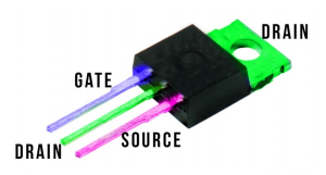
 The Mosfet is a switch. Normally, the DRAIN and SOURCE pins are not connected. So what you have is a switch in the off position.
When a voltage is applied to the GATE pin, the DRAIN and SOURCE are connected. So the switch is in the on position.
As we use it in this tutorial, the voltage to the GATE is supplied by an Arduino pin going HIGH.
The tttttt Mosfet can be used to turn on and off loads BBBBBB. How you wire it to do that is explained below.
Video Demonstration Of Mosfet With Pixel LED strip.
Video in editing
How To Wire A Mosfet For Use
Wiring Explanation
I will go from the top down.
There is a terminal connector to which the load power supply attaches. Typically between 3 and 12 volts.
The next terminal block is used to connect the load. In this case it is an LED. Were it an inductive load, a diode would have to be added around the load.
There is a resistor shown. Its value depends on the load power supply and the LED specifications.
The gate of the Mosfet attaches to the gate signal terminal through what is known as the gate resistor. I use a 270 ohm resistor.
A 10k pulldown resistor is added to keep the gate from floating.
Mosfet Wiring A Second Time
Because the pins on a Mosfet float between on, off and in-between, it is necessary to force the Mosfet to off until the gate voltage is high enough to turn the Mosfet on. This is done by adding a 10k Ohm resistor, known as a dropdown resistor, connected between the Arduino and the gate resistor and ground.
If you are going to control a motor, you must add a diode around the motor in order to block reverse current that is generated when the motor slows.
If you are controlling LEDs only, the diode is not necessary,
Mosfet Operation
 On the left the gate voltage is low. The Mosfet does not complete the circuit from the power source to the drain pine and on to the ground.
On the right, when gate voltage is applied, the Mosfet passes current from the source pin to the drain. The circuit is completed and the LED turns on.
Contact And Feedback
Your questions and comments help us clarify and upgrade the information presented. Even if you find this helpful, please tell us.
Please let us know if this page has been helpful And if you have questions or suggestions, use this spam free system.
Or use the green WhatsApp button that is to the right.


