How To Use Rectifier Diodes To Make An
OR Logic Gate
What’s In This Page?
Instructions for making an OR logic gate using diodes. Includes video explanations and demonstration.
The Latest Information
Anything new and page updates are posted on Twitter (now X) and Facebook.
It is easy to keep up with the latest by following us on either of them.
What This OR Gate Does
Making The Gate
For implementing an OR logic gate using 12v 3 amp diodes, you typically use standard silicon diodes, such as 1N4148 or 1N4001. Zener diodes and Schottky diodes are not typically used for basic logic gate implementations due to their different characteristics.
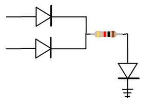
Here’s a basic schematic for implementing an OR gate using diodes:
Additional Information
Video 1 –
Video 2 –
Video 3 –
Video 4 –
Contact And Feedback
Your questions and comments help us clarify and upgrade the information presented. Even if you find this helpful, please tell us.
Please let us know if this page has been helpful And if you have questions or suggestions, use this spam free system.
Or use the green WhatsApp button that is to the right.


