How To Make A Multi-Use Arduino Utility Board For LED Control
page update in progress
What’s In This Page
This is a directory page with information related to operating retro trains, operating narrow gauge train lines and train museums. There are also selected video insertions.
If you are using a phone, at the bottom of the page there are links to many supplies for modelers. Otherwise those links are in the sidebar to the right. You can also find other information by using the search function that is in the navigation bar above.
The Latest Information
Anything new and page updates are posted on Twitter (now X) and Facebook.
It is easy to keep up with the latest by following us on either of them.
A tutorial for making circuit using a circuit board that will provide versatility as well as save you time and labor.
Features
- Control Up To 14 LEDs
- Uses Arduino Mini Pro
- Use with programs of your choice
- Screw terminal connector for easy connecting external elements
- Power on/off direct or via switch
- Two analog input screw terminal connections
- Drop down resistors on Analog input pins
- Professional made circuit board drastically reduces assembly time and labor
The Circuit Board
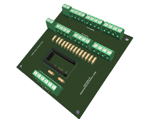
This image shows the circuit board prior to adding the necessary parts. Note how it is extensively labeled to make parts placement easy for you.
After you insert and solder the parts in place, this is what the board will look like. The pins of the Arduino Mini Pro are finally inserted into the DuPont pin sockets.
You can get the board and all the parts here.
Video Demonstrations
This video shows the board lighting leds in rooms of a building.
The Programs
The circuit is designed to display up to 14 LEDs as dictated by the program you load on the Arduino board. The program that load depends on what you intend to do.
You can also program it to toggle another program on an externally connected board.
How to load a program on the board is here. YYYY
Assembly
All connections between parts are made via traces on the circuit board. The circuit board shows exactly where the elements are placed on the board,
So it is a simple matter of inserting the parts, soldering them in place with a fine point soldering tip on which there is a minuscule drop of solder and finally trimming off any protruding wires or pins to a comfortable length.
Solder pins to the Arduino mini.
The Arduino Mini comes without pins attached.
Add the resistors to the circuit board
Solder resistors in place
Cut DuPont pin sockets to proper length
The Arduino Board connects to the circuit board via DuPont pin headers.
Cut them to length and solder them to the circuit board.
Connect the screw terminals
The screw terminals come as 2 pin units. They are designed to be joined by using the slots on each side. So, for example to make a 4 pin screw terminal, join two two pin terminals.
And the screw terminals to the circuit board
And the capacitor in the circuit board and solder in place
All The Solder Joints
Check Continuity
Insert the Arduino mini and to the DuPont pin sockets.
Operation
The program on the board can be controlled manually with the switch.
The switch can be bypassed by using a 5v signal from another board. A 270 ohm resistor should be inserted in the connecting wire.
There are two analog input pins that can, once the board is powered up, to toggle program operations.
Feedback
Your questions and comments help us clarify and upgrade the information presented. Even if you find this helpful, please tell us.
Please let us know if this page has been helpful And if you have questions or suggestions, use this spam free system.
Or use the green WhatsApp button that is to the right.


