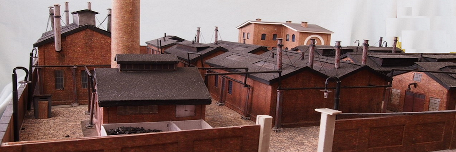
How To Realistically Animate Your Diorama With An Event Timer
What’s In This Page
This is a directory page with information related to operating retro trains, operating narrow gauge train lines and train museums. There are also selected video insertions.
If you are using a phone, at the bottom of the page there are links to many supplies for modelers. Otherwise those links are in the sidebar to the right. You can also find other information by using the search function that is in the navigation bar above.
Also In Addition To What’s In This Page, What This Site Can Do For You
If you are a model train enthusiast, modeler, diorama maker, or interested in making Arduino projects the easy way, there is categorized information for you here. Click Here.
The Latest Information
Anything new and page updates are posted on Twitter (now X) and Facebook.
It is easy to keep up with the latest by following us on either of them.
A tutorial for making circuit using a circuit board that will provide versatility as well as save you time and labor.
A simple Arduino circuit that you can use to set up a sequence of timed events. You set the time of occurrence and the duration of each.
Use this for timing a sequence of thunder storms, light displays, animated activities, sounds, music etc.
Features
A circuit board that toggles functions on another board or boards
Starts and stops 17 events.
Each event start and stop time controlled independently.
Start and stop times can be either fixed or random
Fully customizable program – Click Here
Video Demonstrations
First let’s look at what this timer can do.
These videos show how this works in two of my dioramas.
Simple Animation
 This video shows you a rather simple application of this event timer. You’ll see lights cycle on and off and track lights etc. fade in and fade out.
Click on the image watch the show.
Impressive Animation
 This shows you what you can do if you really take the time with this and make a diorama that is truly impressive.
Click on the image watch the show.
Gather the parts
Assembly
All connections between parts are made via traces on the circuit board. The circuit board shows exactly where the elements are placed on the board,
So it is a simple matter of inserting the parts, soldering them in place with a fine point soldering tip on which there is a minuscule drop of solder and finally trimming off any protruding wires or pins to a comfortable length.
Solder pins to the Arduino mini.
The Arduino Mini comes without pins attached.
Add the resistors to the circuit board
Solder resistors in place
Cut DuPont pin sockets to proper length
The Arduino Board connects to the circuit board via DuPont pin headers.
Cut them to length and solder them to the circuit board.
Connect the screw terminals
The screw terminals come as 2 pin units. They are designed to be joined by using the slots on each side. So, for example to make a 4 pin screw terminal, join two two pin terminals.
And the screw terminals to the circuit board
And the capacitor in the circuit board and solder in place
All The Solder Joints
Check Continuity
Insert the Arduino mini into the DuPont pin sockets.
The pixel connection connects to the WS2812B led strip.
Connected to external animation control boards.
The Program
Operation
Connect a 5 volt power supply. And SPST switch where indicated.
When power is applied to the event timer it starts through its loop. It will loop through the 24 hour cycle.
Remember to adjust that 24 hour cycle to the time you wish it to operate in real time. That is in the instructions.
This cycle will repeat as long as power is applied to the event timer.
Feedback
Your questions and comments help us clarify and upgrade the information presented. Even if you find this helpful, please tell us.
Please let us know if this page has been helpful And if you have questions or suggestions, use this spam free system.
Or use the green WhatsApp button that is to the right.


