

How To Control DC Motors With An L239D Motor Controller
What’s In This Page
An explanation of how an L239D is wired to control a DC motor plus how to use a motor controller circuit board that makes it easy to control 2 DC Motors
These are arranged in two sections. First the explanation and then, below that how to make and use a motor controller circuit board.
If you are using a phone, at the bottom of the page there are links to many supplies for modelers. Otherwise those links are in the sidebar to the right. You can also find other information by using the search function that is in the navigation bar above.
The Latest Information
Anything new and page updates are posted on Twitter (now X) and Facebook.
It is easy to keep up with the latest by following us on either of them.
A tutorial for making circuit using a circuit board that will provide versatility as well as save you time and labor.
Pinout And Pin Functions For an L239d Motor Controller
The L293D is a popular dual H-bridge motor driver IC that is commonly used to control the direction and speed of DC motors. It can also be used to control other inductive loads such as solenoids. The L293D typically comes in a 16-pin DIP (Dual Inline Package) or similar package. Here are the functions of each pin on the L293D IC:

1. Enable 1 (EN1): This pin is used to enable or disable the motor driver for the first motor (typically referred to as Motor 1). When this pin is high (usually connected to a logic high voltage like +5V), the motor driver is enabled, allowing the motor to operate. When it is low, the motor driver is disabled, and the motor comes to a stop.
2. Input 1 (IN1): This pin is used to control the direction of Motor 1. By providing different logic levels to this pin, you can make the motor turn forward or reverse.
3. Input 2 (IN2): This pin is also used to control the direction of Motor 1. It works in conjunction with IN1 to determine the motor’s direction.
4. Output 1 (OUT1): This pin is connected to one terminal of Motor 1. Depending on the logic levels applied to IN1 and IN2, this pin will output a voltage to drive the motor in the desired direction.
5. Output 2 (OUT2): This pin is connected to the other terminal of Motor 1. It works in conjunction with OUT1 to control the direction and speed of Motor 1.
6. Ground (GND): This is the ground reference pin, which should be connected to the common ground of your system.
7. VCC1: This pin is used to supply power to the internal logic circuitry of the motor driver for Motor 1. It is typically connected to a positive voltage source, often +5V.
8. VCC2: This pin is used to supply power to the motor itself for Motor 1. It is connected to a voltage source that matches the motor’s operating voltage. This allows you to control motors with different voltage requirements.
9. Input 3 (IN3): This pin is used to control the direction of Motor 2, similar to IN1 for Motor 1.
10. Input 4 (IN4): This pin is used to control the direction of Motor 2, similar to IN2 for Motor 1.
11. Output 3 (OUT3): This pin is connected to one terminal of Motor 2, similar to OUT1 for Motor 1.
12. Output 4 (OUT4): This pin is connected to the other terminal of Motor 2, similar to OUT2 for Motor 1.
13. Enable 2 (EN2): This pin is used to enable or disable the motor driver for the second motor (Motor 2), similar to EN1 for Motor 1.
14. Not Connected (NC): This pin is not connected to any internal function and is typically left unconnected.
15. Ground (GND): Another ground reference pin, connected to the common ground of your system.
16. Vs: This pin is used to supply the motor driver with the motor voltage (which can be higher than the logic voltage supplied to VCC1 and VCC2) for Motor 2.
By controlling the logic levels on the input pins (IN1, IN2, IN3, IN4) and enabling/disabling the motor drivers (EN1, EN2), you can control the direction and speed of two motors independently using the L293D IC. The outputs (OUT1, OUT2, OUT3, OUT4) drive the motors based on the input signals.
How To Make And Use A Motor Controller Circuit Board.
The Circuit Board
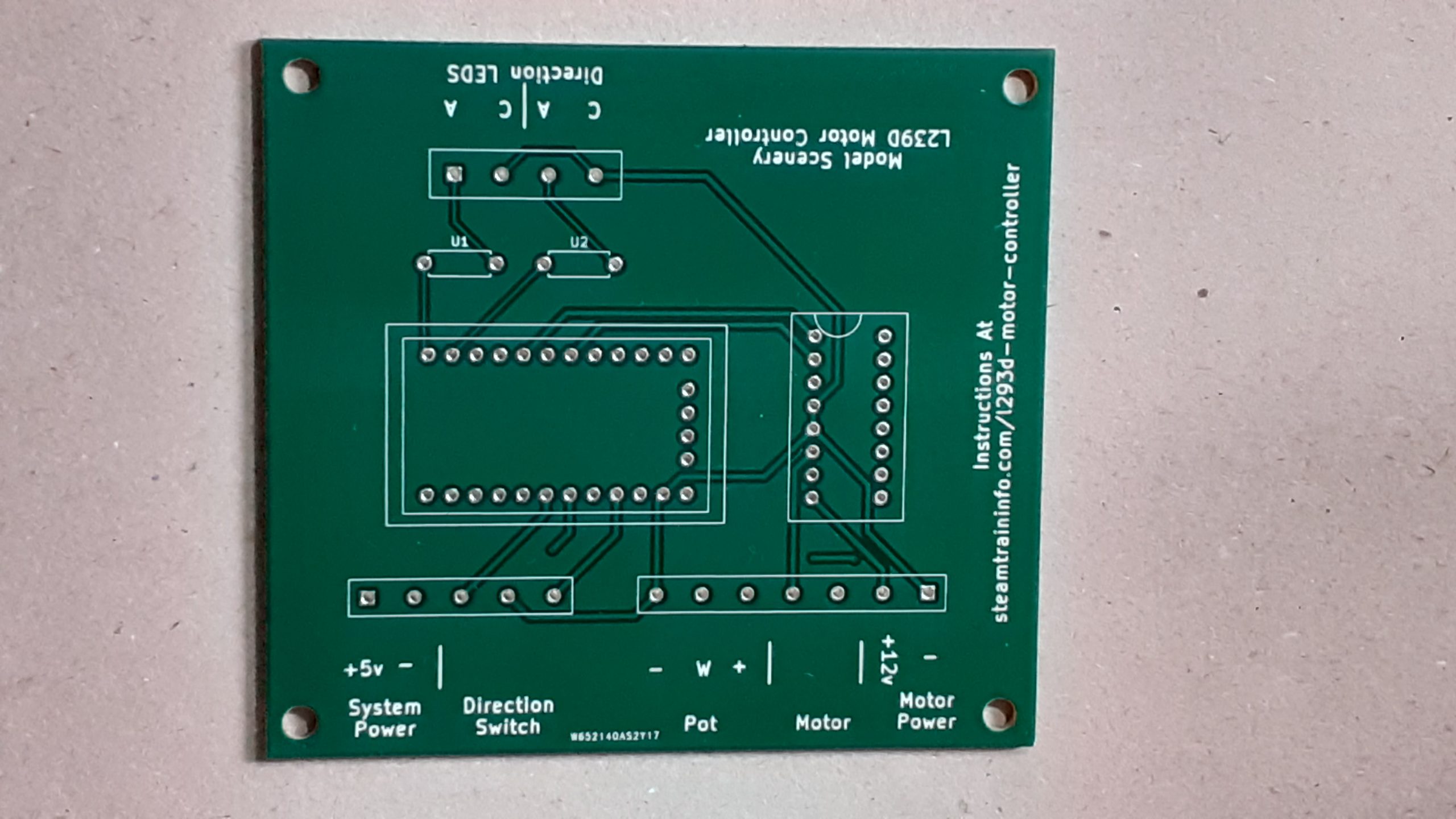 This is the circuit board that makes it easy for you to make a motor controller.
It saves you time and eliminates mistakes. You do not have to do any wiring. All connections are made internally on the board.
The Parts
 These are the parts included in the kit. You can get the kit here. MMMMM
The Assembled Motor Controller
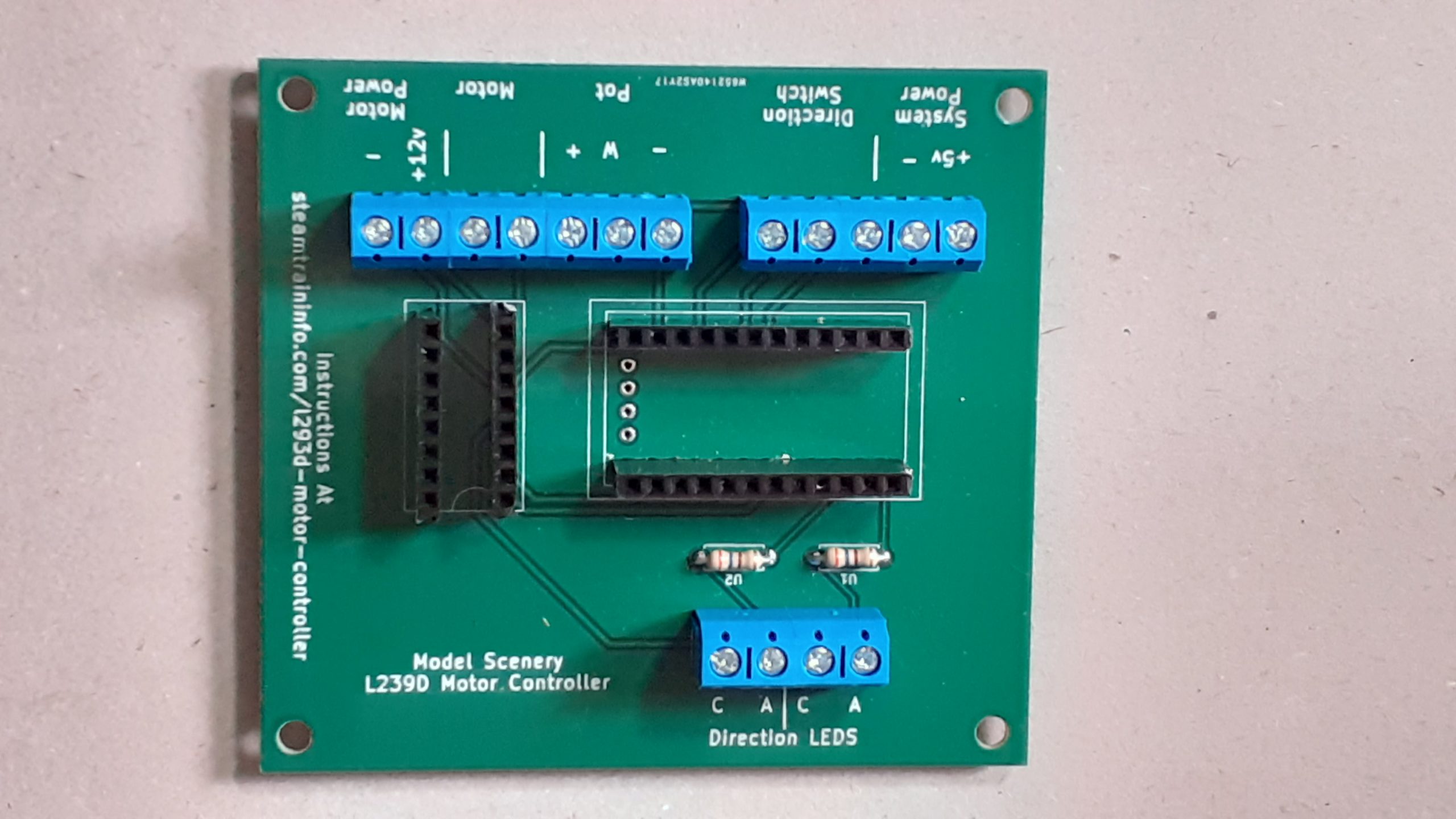 All that you have to do is insert the parts in the designated holes and solder them in place.
The Controller Ready To Go

All the parts are in place. Now it is a matter of using the FTDI programmer to load your driver code on the Arduino board.
Make power and other connections where indicated on the edge of the board.
Feedback
Your questions and comments help us clarify and upgrade the information presented. Even if you find this helpful, please tell us.
Please let us know if this page has been helpful And if you have questions or suggestions, use this spam free system.
Or use the green WhatsApp button that is to the right.