
How To Add A Multiple Flash Thunder And Lightning Storm To Your Scene
What’s In This Page
Page Update In Progress
This page provides a step-by-step guide on how to build a thunderstorm control board that will play thunder audio files and control lightning strikes. The board features three bright lightning flashes using 12v LED strips, and lightning flashes when thunder audio exceeds a programmable threshold. The LED strips flash randomly, and the thunder and lightning storm starts at random intervals and lasts for random intervals.
If you are using a phone, at the bottom of the page there are links to many supplies for modelers. Otherwise those links are in the sidebar to the right. You can also find other information by using the search function that is in the navigation bar above.
The Latest Information
Anything new and page updates are posted on X (formerly Twitter), Rumble and Facebook.
It is easy to keep up with the latest by following us on either of them.
Free Help
Features
- The display is 3 random flashes of white lightning strikes.
- The strikes occur when the level of the thunder sound exceeds a given threshold.
- The lightning strike rate and sound effect intervals can be adjusted.
- The article includes instructions on how to change the code and load it onto the Arduino boards.
Video Demonstrations
 This video shows a scene using this system. . Click here to watch.
And here is a video that shows the board and lightning strips in action.
Add video
How It Works
 The Storm Timer

To avoid overexposure of the thunderstorm and boredom, a thunderstorm event timer starts and stops the storm.
When the storm is switched on, the event timer randomly waits 3 to 5 minutes to start a storm. The storm then lasts a random time of 1.5 to 2.5 minutes.
This cycle continues as long as it is switched on.

The Flash Controller
The lightning strikes when the sound from the mp3 player exceeds a threshold of 750 in the program, You can increase that number to decrease the number of flashes and likewise increase them by decreasing the number.
The flash rate is set at a random interval of 20 to 30 milliseconds. Change that by changing randNumber(20,30) in the program
The Thunder Sounds
The time between thunder sounds can be increased by changing the sound peaks on the SD card. Use the free program Audacity to do that.
How It Works
When power is turned on, a storm timer starts running. It decides when the storm should start, how long it should last and when it should stop. You can vary the cycles anyway you wish. The instruction manual tells you how to do this.
When it decides that a storm should start, it applies power to the audio player and Lightning Flash Controller.
The Lightning Flash Randomizer randomly decides which LED strips light and the duration of lighting. These can be varied as you wish.
The strips do not flash until the sound or the thunder reaches a threshold level. The Lightning Flash Randomizer.reads the level continuously through the Lighting Trigger wire. When it reads the threshold level or above, it starts flashing the lights.
Assembly
All connections between parts are made via traces on the circuit board.
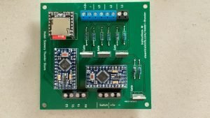
The circuit board shows exactly where the elements are placed on the board,
So it is a simple matter of inserting the parts, soldering them in place with a fine point soldering tip on which there is a minuscule drop of solder and finally trimming off any protruding wires or pins to a comfortable length.
Parts
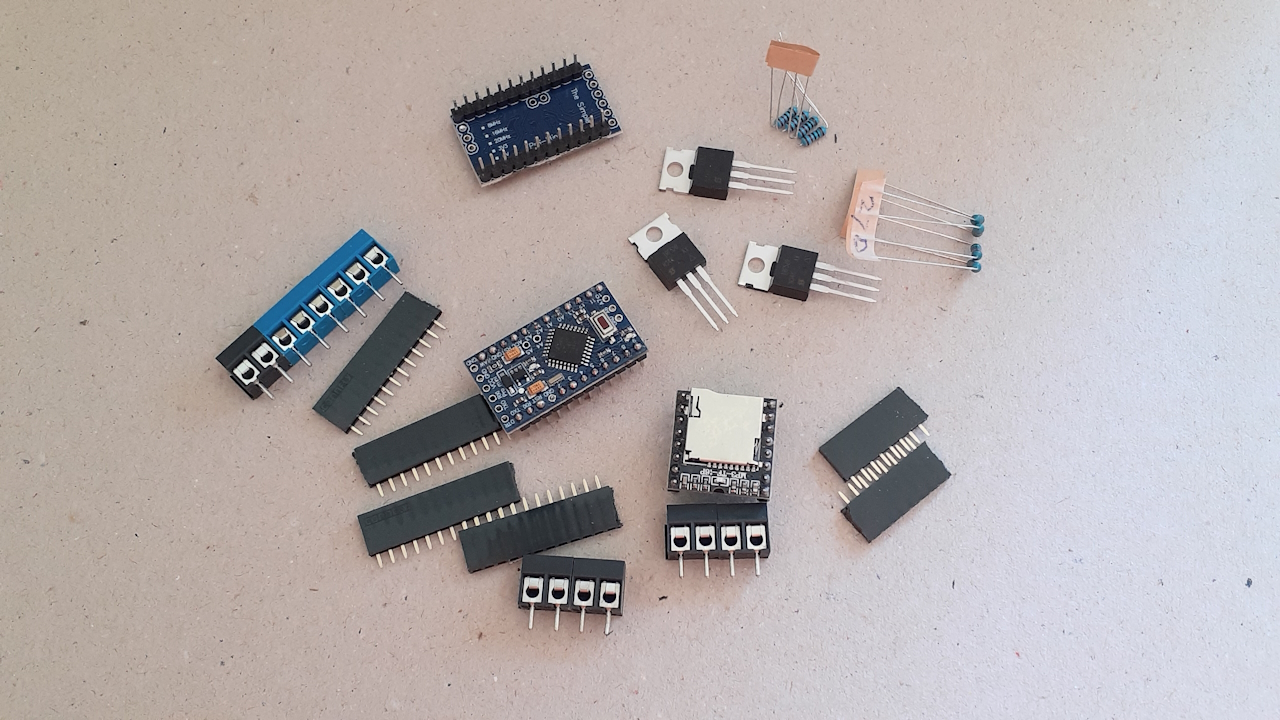
 This image shows the complete selection of parts that come in this kit. The source of the kit is here. Click Here.
Preparation
 For ease of assembly, prepare the parts for soldering to the board.
The screw terminals come as 2 pin units. They are designed to be joined by using the slots on each side. So, for example to make a 4 pin screw terminal, join two two pin terminals.
The pins on the DFPlayer and Arduino board connect to the circuit board via Dupont pin sockets. Cut the pin sockets to length.
Bend the resistor wires to a 90 degree angle from the resistor body. Be careful. There are 270 and 10k ohm resistors. They look alike. Work with one set at a time.
Solder Resistors To Board
 It only take a fine bit of solder to make the weld. I use .7 mm solder wire for all my circuit board work.
Be sure that the joint is well bonded. Too little heat or a short tap will put solder on the wire or pin and not the circuit board pad. Be careful and patient.
Solder Pin Headers To Board
 Some blue tack on the ends of the pin headers will keep them in place. Be sure to set them flat and square.
To square them, consider inserting the pins from the Arduino board into the pin headers.
Solder The Mosfet To The Board
 The gate pad is labeled on the board. Be sure to insert the gate pin into that pad.
If you are unsure which is the gate pin, read this reference material. Click Here
CAUTION: The heat sink on the Mosfet gets HOT! Wait a bit after soldering before you touch it.
Solder The Screw Terminals To The Board.

There is quite a bit of metal in the terminals that acts as a heat sink. Hold the soldering iron tip in place for a bit to be sure of a good weld.
Insert the MP3 Player Arduino Boards Into The Pin Sockets
The Arduino boards are labeled and programmed. After testing, you can change those programs to suit your needs. How to do that is shown here. Click Here
The SD card is loaded with the recommended sounds for this project. If you wish to use different thunder sounds, this page shows how to load them on the card .
External Connections
This storm can be controlled by manual switch.
The switch connections are labeled SW1 and SW2 . If you use a switch that switch is usually located on a control panel which is likely to be some distance from the circuit board.
 You can bypass the switch and start the system as soon as power is supplied by connecting the power supply as shown in the image to the left.
Attach the speaker to S+ and S-. The + and – match those on the speaker. Speakers have an upper limit of 3 watts.
If you wish more volume, add a 5v amplifier. How to do that is here.
TX and RX are connections for a Bluetooth module. By using such a module you can play sound on a Bluetooth speaker that you place at a removed location. How to do that is here.
The boards and MP3 player use 5v DC. Connect the board to a 5 volt DC power supply via the labeled terminals.
The LEDs use 12 volt power. All the boards use 5 volt power. So the LEDs are connected to a separate 12 volt power source. Connect to a 12 volt DC power supply via the labeled terminals.
Making the Changes And Loading the programs.
How to change an Arduino program without any knowledge of programming, go here.
How to reload a program on an Arduino Mini Pro is here.
Free Help