

LED Pixel Controller For LED Using WS2812B Pixel Strips
What’s In This Page
A tutorial for making a pixel controller that will control your own pixel strip light display, run FASTLED programs and control pixel strips from an android phone or tablet.
Links to details on using each of these methods with video demonstrations and apps for your android phone.
If you are using a phone, at the bottom of the page there are links to many supplies for modelers. Otherwise those links are in the sidebar to the right. You can also find other information by using the search function that is in the navigation bar above.
Also In Addition To What’s In This Page, What This Site Can Do For You
If you are a model train enthusiast, modeler, diorama maker, or interested in making Arduino projects the easy way, there is categorized information for you here. Click Here.
Pixel LED Control Board
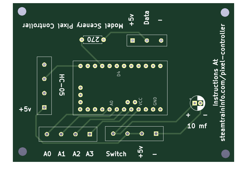 To assure reliability and save you time, this is the circuit board that we use before elements are added.
Why do we use circuit boards? Wiring a prototype board takes precious seconds of our life that we can never recover. When we use a circuit board, we don’t waste those precious seconds.
And the end product is professionally reliable and perfect.
When elements are added, clearly labeled screw terminals make it easy to connect wires.
![]() You can control the program either manually with a switch or by attaching an HC-05 receiver module that will accept commands from either an android or window app.
You can control the program either manually with a switch or by attaching an HC-05 receiver module that will accept commands from either an android or window app.
Parts And Pieces
All the parts and pieces come, along with apps and programs, in a kit that you get here. Click Here MMMM
Programs
An app for using a color wheel on an android phone or tablet. Click Here
An app that allows you to choose one of 3 Fasled programs that you have loaded on the board. Click Here
A complete tutorial series and access to Fastled programs that you can load on the board and then start and stop buy using a switch connected to the board. Click here.
Assembly Tips
Save a lot of time by preparing the elements all the elements before you start soldering.
Connect the individual screw terminals using the tabs on their sides.
Bend the resistor wires to a right angle.
Cut the DuPont pin headers to the right length.
When all that is done, solder the resistor and capacitor in place.
Solder the pin headers in place.
Finally, solder the screw terminals in place.
If your Arduino board was not per-assembled, assemble it and add the code of your choice.
Feedback
Your questions and comments help us clarify and upgrade the information presented. Even if you find this helpful, please tell us.
Please let us know if this page has been helpful And if you have questions or suggestions, use this spam free system.
Or use the green WhatsApp button that is to the right.