

How To Make A Thunder And Lightning Storm With LED Light Bulbs.
What’s In This Page
A storm effect that is particularly useful for uncovered model train layouts such as shelf layouts.
Learn how to make a captivating thunder and lightning storm effect using 12-volt LED light bulbs or pixel strips for model train layouts. This tutorial features random storm occurrences, realistic lightning flashes, customizable thunder audio, and options for Bluetooth connectivity. Follow the step-by-step assembly guide, complete with a video demonstration, to bring your model train layout to life with this impressive storm simulation.
If you are using a phone, at the bottom of the page there are links to many supplies for modelers. Otherwise those links are in the sidebar to the right. You can also find other information by using the search function that is in the navigation bar above.
Also In Addition To What’s In This Page, What This Site Can Do For You
If you are a model train enthusiast, modeler, diorama maker, or interested in making Arduino projects the easy way, there is categorized information for you here. Click Here.
The Latest Information
Anything new and page updates are posted on X (formerly Twitter), Rumble and Facebook.
It is easy to keep up with the latest by following us on either of them.
Free Help
Features
Uses any type 12 volt LED light bulbs
12 v LED pixel strips can also be used.
Storms occur randomly according to changeable storm timer settings
Bulbs flash randomly for full lightning effect
Flashes occur when thunder audio exceeds a defined threshold.
Thunder audio on 32 GB SD card can be changed to your audio
Can conned Bluetooth transmitter to play audio on remote Bluetooth speaker.
Has two connections that go high when the player is powered up. They can provide 5 volt trigger for optional external applications.
Can connect single mini speaker for monaural sound or 5v amplifier for increased volume on one or two speakers. With 5v amplifier, stereo sound is possible.
Can turn on and off using remote manual switch or an event timer.
Screw terminal connectors for all external connections
All internal wiring connections built into circuit board for easy assembly.
Video Demonstration
to be added
The Board
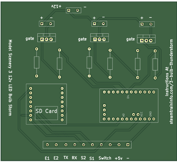
This project uses a kit that is based on a kit that includes the board and all the parts necessary to control the LEDS.
Everything about the kit is provided at this link. NNNNN
Assembly
All connections between parts are made via traces on the circuit board.
The circuit board shows exactly where the elements are placed on the board,
So it is a simple matter of inserting the parts, soldering them in place with a fine point soldering tip on which there is a minuscule drop of solder and finally trimming off any protruding wires or pins to a comfortable length.
The screw terminals come as 2 pin units. They are designed to be joined by using the slots on each side. So, for example to make a 4 pin screw terminal, join two two pin terminals.
The Arduino board comes without pins. Cut pin headers to proper lengths and solder them in place.
The pins on the DFPlayer and Arduino board (now with pins you just soldered on) connect to the circuit board via Dupont pin sockets. Cut the pin sockets to length and insert the pins into the sockets.
The sockets will be soldered to the circuit board. With the pins or the DFPlayer and and Arduino board inserted, you can be sure that the pin sockets will be vertical when soldered to the board.

The board shows where the Mosfet GATE pin should be inserted. The image to the left shows which of the 3 pins is the gate pin.
Also look at the board image above to double check that you have the gate properly positioned.
Now add all the elements to the board and solder in place.
The SD card is loaded with the recommended sounds for this project. If you wish to use different thunder sounds, this page shows how to load them on the card . You can get other sounds here. Player Sounds
The Arduino mini pro is fully programmed.
Operation
This storm is controlled by a manual switch. The connections are labeled Switch . (To control it via another micro controller just connect the trigger from that controller to the switch .) That switch is usually located on a control panel which is likely to be some distance from the circuit board.
Attach the speaker to S+ and S-. The + and – match those on the speaker. Speakers have an upper limit of 3 watts.
If you wish more volume, add a 5v amplifier. How to do that is here.
TX and RX are connections for a Bluetooth module. By using such a module you can play sound on a Bluetooth speaker that you place at a removed location. How to do that is here.
Connect to a 5 volt power supply via the labeled terminals.
You connect a 12v power supply where indicated.
Free Help