

About Model Railroad level crossing gates types and operation. A full review of the various types of crossing gates and how to make them. First we show you our full video series on level crossings and then detailed information in text format.
Additionally there are links to very detailed tutorials covering all aspects of making a level crossing.
Types Of Level Crossing Gates
 Gate types are region and era dependent. The image on the left shows a gate used in Poland in 2022. It consists of a simple machine in a metal box that raises and lowers a lighted pole.
The machine boxes vary in shape and size. But generally they are simple affairs with square corners that are easy to make and easy to maintain. And they are easy for modelers to make and use.
 Here is another on the same line about 2 kilometers down the line. The barrier is a single, unlighted board.
And note the very small gate operating mechanism.
A very prominent warning bell can be seen at the top of the light pole.
 The model to the left is a beautiful example of a squared gate machine with a bell.
The model maker too a lot of time to add many details that one does not normally see on prototypes. But it definitely does make for an interesting model.
 This image shows a early to mid 1900’s, hand operated gate at a narrow gauge train museum in Wenecja Poland.
The barrier mechanism is remotely operated by cable that the gate guard controls with the hand cranked unit on the left. The cable moved gates on both sides of the track.
The barrier is an unlighted pole.
 And here is one at the Whippany Train Museum It is hand operated.
The Whippany train museum has detailed historical information about how grade crossings were managed. It might be well worth your time to visit their site.
 Finally here is a gate typical of many modern US and European railroads. Various styles of this are available commercially. A model of the one shown can be purchased here.
 Finally here is an interesting variant. I have long lost information about who sent me this image and who the modeler is who made it.
Operation Of Crossing Gates
Model railroaders generally use some form of proximity detector on either side of the crossing. They trigger the operation of servo motors whose rotation speed is set to provide realistic gate operation.
These same sensors can also control flashing lights and alarm bells.
The number of sensors and servos depends on the number of tracks, and gates in the crossing.
You can purchase level crossing control boards. Since they are rather expensive, many modelers prefer to make their own. Each of the links in the lower part of this page take you to specific instructions for each type crossing, And you can also get a control circuit kit through one of those links.
Crossing Gate Installation
 The gates are moved by a wire connected to a servo mounted under the crossing. The image to the left shows the general concept.
Under the crossing are servos that connect to the gate barriers by wire. The servos are controlled by a circuit board that also synchronizes the warning lights and bells with the gates.
The controlling circuit board can be purchased or easily made.
Instructions on how to make it are in a tutorial below.
Those same instructions come with a kit containing the parts to make the circuit board that can get here.
Scratchbuilding Crossing Gates
Coffee sticks and wooden knives can be used to make solid machine bases. They are easily laminated and sanded to shape.
Other materials such as styrene, acrylic sheet, basswood, pine and birch are good.
Some Examples Of Model Crossing Gate Mechanisms
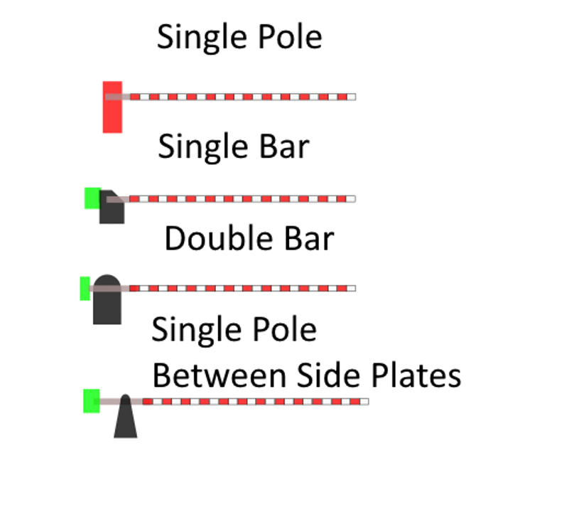
The image to the left shows some examples of gate mechanism shapes.
An example of the single pole mechanism is shown in the first image in this page.
The one labeled single bar has the bar on one side and the counter weight on the other.
The one labeled double bar has a bar and counter weight on each side of the mechanism. The Whippany gate shown above gives you a prototype view.
The single pole between the side plates mechanism can be modified to look like the cable operated unit shown above. But it can be used as a simple stand alone unit.
Prototypes are usually measured in whole numbers. If you scale them to model sizes, the dimensions end up being in decimals. For example, 1 meter in 1/1 is 11.4943 in 1/87. Practically speaking, unless you are working with brass or card, it is best to round off to 11 mm. You won’t see it on your model.
Making Machine Operated Crossing Gate Operating Mechanisms
These extremely easy to make.
Laminate coffee sticks, disposable wooden forks, or other hardwood to achieve the basic dimensions. Your bar should be 48 inches, or a bit lower, above the pavement. That will be your baseline to set your machine height.
Sand the laminated piece to the shape.
Drill a hole for the shaft.
Grade Crossing Barriers
The barrier will take a bit more time.
The flat barrier bars are easily made from veneer, brass or shaped hardwood. A wooden disposable knife, cut and sanded thin makes a great wooden bar.
The counterweight and barrier connectors are made from brass filed to shape. The video in the playlist above shows you how it is done.
To avoid painting the red and white stripes, print them on photographic paper. Attach them to the flat bar with double sided tape. If you would like a .pdf file with the stripes in color, which stripes you can print in your scale, contact us.
A round bar, if you wish to add lights, should be hollow so that you can run wires through the center. Brass rod is a first choice. To paint it, you must apply a primer. To avoid brush marks, use Rustoleum spray metal primer.
Then apply the white. Use a white spray. Mask and then spray red. Use a couple THIN coats so that the red does not leach under the red.
Set the barrier length to your road width always keeping the last stripe at the center of the road white.
Crossing Gates Basics
The next two images give you basic information about gates and lights. The images and information are summarized from Federal Highway Administration, Railroad-Highway Grade Crossing Handbook – Revised Second Edition August 2007. It is US related but much of the information is universally applicable. Do take the time to read it.
For summary information, click on each of the images.


Grade Crossing Tutorials
To stay up to date and be notified as we add to this series, subscribe and click on the bell in one of the videos below.
[embedyt] https://www.youtube.com/embed?listType=playlist&list=PLLYkOTQM-OSWNfQzx2tohwerBRI8dxwa2&layout=gallery[/embedyt]
Related Level Crossing Pages
How To Make An Automated Level Crossing –
How To Install A Level Crossing In Your Layout. –
Arduino How To Install An IR Sensor Under Track
How To Make Level Crossing Gates –
How To Make Level Crossing Flashing Lights–
How To Make Automated Level Crossing Flashing Lights –
How To Make Automated Level Crossing With Flashing Lights Plus 2 Gates For 1 To 3 Tracks –
How To Make Automated Level Crossing With Flashing Lights Plus 4 Gates For 1 To 3 Tracks –
How To Add Warning Bells At Model Railroad Level Crossings –
How To Make A Level Crossing Control Circuit Board –
How To Install Automated Level Crossing Operating Mechanism