

Wiring diagrams and instruction for installing spotlight block signals on a model railroad layout.
Installation can be made on a single track loop and on at point to point multi-direction single track.
 This installation requires the use of the the Model Scenery Signal Driver circuit board.
It can drive 3 three color LEDs and 2 color LEDs installed in a searchlight type signal head.
A list of all uses is here.
- Red, Yellow and Green – 3 Light signals. Click For Instructions
- Red, Yellow and Green And Red Green – 1 Light Spotlight signals. Click For Instructions
- Red and Green – 2 Light signals. Click For Instructions
- PRR Position Light signals. Click For Instructions
It can be purchased here. MMMMMM
The Circuits
For 2 color signals a modified Model Scenery Block Signal Driver must be used. The modification consists of replacing R6 with a jumper and removing D2.This is done so that the Green LED remains ON when the YELLOW input to the signals goes LOW.
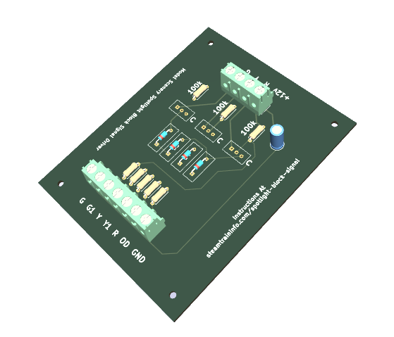 The modified signal driver is shown to the left. To avoid confusion, it is called the Model Scenery Spotlight Block Signal Driver.
It can be purchased here. PPPPPP
2 Colour Red Green Signals Using Common Cathode Or Anode LEDs
For a Red Green signal, a two color common anode or common cathode LED is inserted into a spotlight signal face. If you wish a Green Yellow signal, use a three color LED and connect the Yellow lead instead of the Red.
The in the circuit diagram below, the image labeled” 3 Light – Signal Block” is the Model Scenery Spotlight Block Signal Driver . It can be purchased here. PPPPPP
Note how two iN4148 diodes are added to the leads of the LED.

3 Colour Signals Using Common Cathode Or Anode LEDs
This image shows three light wiring. For spotlights, just substitute a 3 color light for the three individual LEds. It uses the unmodified version of the signal driver. The circuit board for that can be purchased here.

Single Track Multi-Directional Track Operations
For Point To Point single track multi-directional operations, use Tumbledown Interlocking.. That is explained here.
General Notes For The Model Scenery Block Signal Drivers
- The signal circuits can be controlled by any device that can pass at least 1 milliamp current and shares a common connection with minus terminal of the signal circuit’s power supply.
- The circuit is designed for a 12 volt power supply voltage and will drive light emitting diodes at approximately 10 milliamps. Other supply voltages and LED currents can be used.
- The values of the current limiting resistors for the LEDs – R4, R6 and R8 – can be changed to achieve the desired brightness from each signal LED. For example;- If the signal LEDs are too bright, external resistors can be connected at the circuit board’s outputs rather than replacing resistors R4, R6 and R8 on the circuit board.- If the signal LEDs are too dark, resistors R4, R6 and R8 can be replaced with resistors of lower value.
- Diodes D1 and D3 at the base circuit of transistors Q1 and Q2 provide an extra voltage drop in the base circuit that allows the transistors to turn off completely. This diode is not needed at the base of Q3.
- The combined current from a DETECT INPUT of one block and the YELLOW INPUT from the previous block is about 2 milliamps. This low current allows the PNP signal circuit to be controlled directly by optoisolators.
- The circuit’s BOD input will operate at properly at voltages of less than 3 volts.
- More than one block can be controlled by a single input device if diodes are used to separate block input devices such as occupancy detectors, toggle switches and computer control systems.
- The signals can be controlled by a dispatcher using toggle switches. In this case no occupancy detectors would be needed.The toggle switches can be used in conjunction with block occupancy detectors.
- Common cathode and common anode connected LEDs can be used for different blocks so that various home built and commercial signals could be used at the same time.
- The circuit can be adapted to drive 2 colour, common cathode connected or common anode connected LEDs to make a Search Light type signal. Diode D2 is removed from the circuit for this application.
Feedback
If need any information, have comments, or have questions, please use this spam free form.