
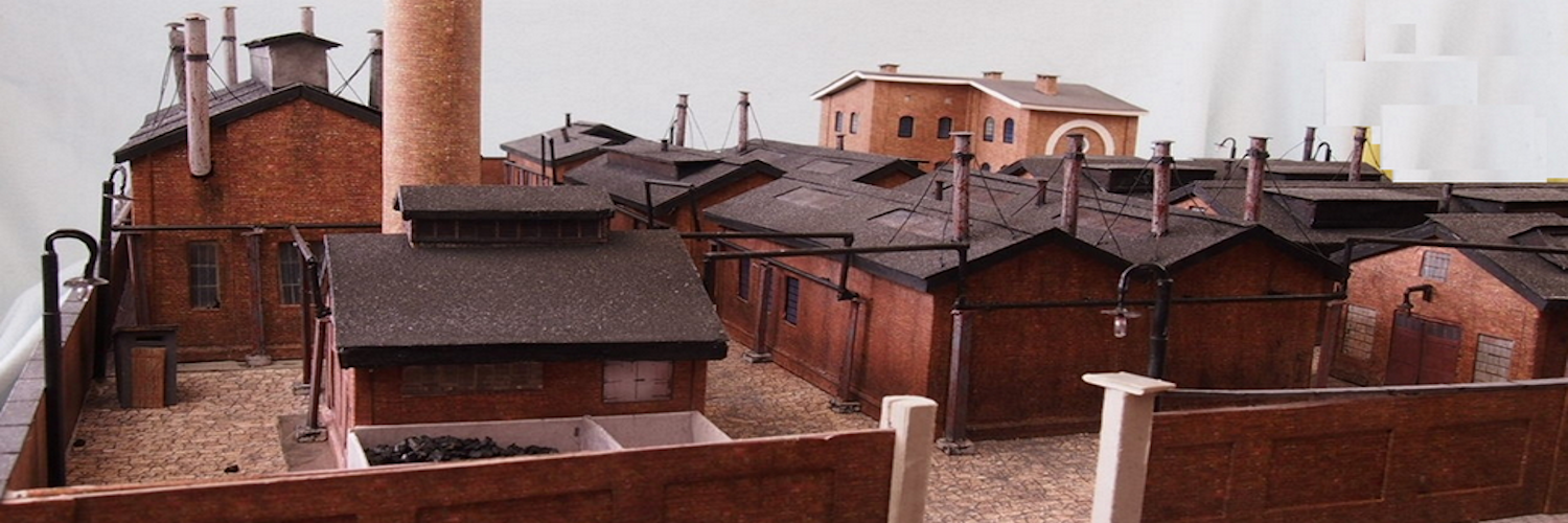
Making model train layouts is a great hobby, automating it will make it a lot better! Let us take a look at some of the advantages of its automation:
- Low-cost operation: The whole layout is controlled by an Arduino microcontroller, using an L298N motor driver, their cost is almost nothing as compared to traditional train control throttles and power packs.
- Ideal to put up at a display: Since no human interference is required to keep a control on the layout, you can use it at a display where you cannot be always present to control the train and the turnouts.
- Great for microcontroller hobbyists: If you are or want to start with Arduino and programming, this is a great project for you to practice your skills.
To start, make sure you have all of the following:
- An Arduino microcontroller board, UNO is preferred.
- An L298N dual H-bridge motor driver board.
- 6 male to male jumper wires.
- 7 male to female jumper wires.
- A screwdriver.
- A 12 volt-DC power supply adapter.
- A track segment with IR proximity sensor attached on the underside(I used a Kato S62 track)
Make an oval loop with a passing siding somewhat as shown above. Make sure the distance between the sensor track and the first turnout the train will cross after crossing the sensor track is greater than the length of the train such that no part of the train is over the sensor track when it crosses the turnout.
: A Circuit Schematic Is Always Helpful

Click on the image to get a full view. Make sure you go through the full circuit schematic and all of the details before proceeding.
Connect the red and the black wires of both the turnouts respectively to each other, resulting in a parallel connection. Then, connect the red wires to the out4 and the black wires to the out3 terminal of the motor driver board.
Connect the power feeder’s white wire to the out1 and the blue wire to the out2 terminal of the motor driver board.
Connect the 12-volt pin to the VIN pin of the Arduino board, the GND pin to the GND pin of the Arduino board, and preferably, the 5-volt pin of the motor driver to the 5-volt pin of the Arduino board.
Connect the VCC pin of the sensor to the 5-volt pin of the Arduino board, GND pin to GND pin of the Arduino board, and the OUT pin to the A0 pin of the Arduino board.
Connect the digital pins of the Arduino board to the input pins of the motor driver board as follows:
- D9 to IN1
- D10 to IN2
- D11 to IN3
- D12 to IN4
After checking all of the wiring connections, place the train on the siding.
Power up the setup and make sure the turnouts get switched to the siding, if not then just reverse the connections of the turnouts made with the motor driver. Also, make sure the train starts to move to forward direction. Reverse the feeder track’s connection with the motor driver if the train moves in the wrong direction.